A pump motor trips on ground fault. All three panel ammeters show the same readings as yesterday, the motor ran normally an hour ago, and nothing obvious looks wrong. Yet something in that circuit detected a few amperes flowing where they should not, against hundreds of amperes of normal load.
That something is often a zero sequence current transformer, or ZSCT. What is a zero sequence current transformer, exactly? It is a ring-shaped current transformer that encloses all the current-carrying conductors of a circuit at once (three phases, plus the neutral in a four-wire system) and measures their vector sum instead of any individual phase current. In a healthy circuit that sum stays close to zero. When insulation begins to fail and current leaks to ground, the balance is disturbed, and the ZSCT sends a proportional signal to a ground-fault relay.
Even a few amperes of leakage can matter. It may be an early sign of deteriorating cable insulation or a failing motor winding, and in some systems it can contribute to hazardous touch voltage or develop into a more serious ground fault. Detected early, it may mean a planned repair. Detected later, it can mean an unplanned outage, motor damage, or switchgear damage. Phase CTs sized for normal load current may not provide the sensitivity needed to detect leakage at this level, which is exactly the gap a ZSCT is designed to fill.
Depending on the drawing or manufacturer, the same device may also appear as a zero-sequence CT, core-balance current transformer, ground-fault CT, or simply Z CT on a one-line diagram.
Key takeaways
- A ZSCT measures the vector sum of all current-carrying conductors that pass through its window.
- Balanced load current cancels inside the core, so the ZSCT can detect ground leakage far below normal load current.
- In four-wire systems, the neutral must pass through the window as well.
- Cable shields, grounding conductors and downstream neutral-to-ground bonds can make an otherwise correct installation misread.
How does a zero sequence current transformer work?
It adds up the currents of all conductors magnetically. In a healthy circuit their fields largely cancel inside the core, leaving the secondary winding with almost nothing to measure; when current leaks to ground, that balance breaks and the secondary produces a signal.
The phase currents are displaced by 120 degrees, and whatever flows out on one conductor comes back on the others. Each conductor still magnetizes the toroidal core, but since the ZSCT surrounds all of them at once, their fields add up to nearly zero flux. A motor drawing 400 A per phase looks, to a correctly installed ZSCT, much like a motor that is switched off. That cancellation is the heart of the zero sequence current transformer working principle.
When insulation breaks down downstream, part of the current escapes to ground through a damaged cable, a wet terminal box or a cracked winding, then returns to the source through the grounding system instead of through the conductors inside the window. The sum is no longer zero:
Ia + Ib + Ic = 3I0
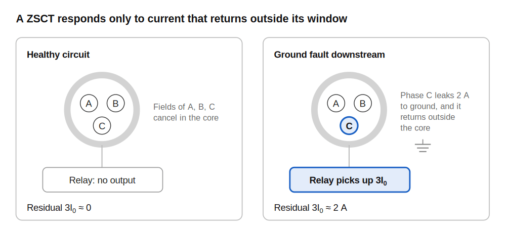
A simple, purely illustrative case: the motor above carries 400 A per phase, a damaged cable leaks 2 A to ground, and the relay pickup is set at 1 A primary. The phase ammeters barely move, while the ZSCT sees the full 2 A and the relay operates.
There are two limits to that simplified picture. Real ZSCTs may produce small residual errors, and installation can add stray signals (more on that below). And a quiet ZSCT only says the currents through its window are balanced. It says nothing about a phase-to-phase fault, an overload or a bad bearing, which other protection has to cover.
What does “zero sequence current” mean outside the textbook?
On site, zero sequence current is current that has left the circuit’s own conductors and is coming back through ground, a cable shield or some other path it was never meant to use. In a three-wire system that usually points to an insulation problem.
The term comes from symmetrical components, a method that splits any unbalanced set of three-phase currents into positive, negative and zero-sequence sets. The positive- and negative-sequence components each sum to zero across the three phases. The zero-sequence part is identical in magnitude and angle on all three conductors, so it has nothing to cancel against.
Relay settings are normally given as residual current, 3I₀, while some short-circuit studies report I₀. A factor-of-three gap between the study and the test sheet is a familiar commissioning headache.
If the phase CTs can calculate residual current, why add a zero sequence CT?
Because a residual connection inherits every mismatch between three separate CTs, and that usually pushes the ground-fault setting higher than sensitive applications can accept.
With the phase CT secondaries connected in parallel (the residual, or Holmgren, connection), 3I₀ is the small difference between three large secondary currents. Ratio and phase angle errors that are harmless for overcurrent protection show up here as false residual current. During motor starting or a phase-to-phase fault, one CT can saturate slightly ahead of the others, and the relay sees a ground fault that isn’t there. Engineers may have to raise the pickup setting to avoid nuisance trips, which can leave low-level leakage undetected.
A ZSCT does the subtraction magnetically, inside one core, before anything reaches the secondary. Relay engineers in North America will recognize the difference in ANSI device numbers: a function fed by a separate ground sensor is usually labeled 50G or 51G, while one calculated from phase CTs is labeled 50N or 51N, depending on the relay manufacturer’s naming convention.
| Approach | How residual current is obtained | If phase CTs saturate unequally | Sensitivity (illustrative, project-dependent) | Where it tends to be used |
|---|---|---|---|---|
| Zero sequence CT (core balance), ANSI 50G/51G | Magnetic summation of all conductors in one core | Not affected by unequal saturation of the separate phase CTs | Can reach fractions of an ampere to a few amperes primary | High-resistance grounded and ungrounded MV systems, motor feeders, cable circuits needing sensitive ground-fault protection |
| Residual connection of three separate phase CTs, ANSI 50N/51N | Electrical summation of three secondary currents | Can produce false residual current | Limited by CT matching, saturation and inrush; set per project | Solidly or low-resistance grounded systems where ground-fault currents are large and phase CTs already exist |
| CT in the neutral-to-ground connection | Measures current returning through the transformer or generator neutral | Depends on the application; it measures source return rather than feeder summation | Good, but sees the whole system rather than one feeder | Backup or overall ground-fault protection at the source |
Open a typical MV switchgear lineup and it is common to find two of these side by side: a ZSCT under each outgoing cable compartment, and a CT in the transformer neutral watching the whole bus as backup.
Where is a zero sequence CT actually used?
Mostly where ground-fault current is deliberately kept small, and where knowing which circuit is leaking matters as much as knowing that something is.
Ungrounded and high-resistance grounded medium-voltage systems fit that description well. A single-line-to-ground fault there may produce only a few amperes, sometimes less, and phase CTs rated for hundreds of amperes cannot resolve that reliably. A ZSCT on each feeder gives the relay a clean measurement to work with.
Whether that is enough to pick out the faulted feeder depends on the system, though. In ungrounded systems the healthy feeders also carry capacitive charging current during a fault, so the relay often needs directional ground-fault protection (ANSI 67N) with a voltage reference, or an algorithm suited to that grounding method. Low-resistance grounded systems are a different story: ground-fault currents there typically reach hundreds of amperes, a residual connection is often adequate, and ZSCTs are added where extra sensitivity is wanted.
A submersible well pump rarely fails in one dramatic moment. Its insulation tends to degrade over months, and leakage creeps up long before a full short circuit. Motor protection relays usually have a dedicated ground CT input for exactly this, and catching the leakage early can mean a rewind rather than a burned stator core.
Mining is a case of its own, since trailing cables on mobile machines are dragged and crushed every shift and many mining regulations require sensitive ground-fault protection on them.
Low-voltage installations use the same idea under other names: conventional GFCIs and RCDs work on the differential-current principle, typically with a small core-balance transformer. Where adjustable pickup and time delay are needed, larger LV feeders and generator circuits often use a separate zero sequence CT with a ground-fault relay.
In inverter-fed, PV or EV charging applications, residual current may also contain DC or high-frequency components, so the sensor and protective device must be specifically rated for the expected waveform. A conventional AC ZSCT should not be assumed suitable for those applications.
Why does a good ZSCT sometimes miss faults or trip for no visible reason?
In most cases the transformer itself is fine and the zero sequence CT wiring around it is not, with the cable shield at the top of the list.
Two different paths are easy to confuse here. The first is the metallic shield (or armor) of the cable itself, which runs through the CT window together with the phase conductors. The second is the separate ground lead, often a braid or pigtail, that connects that shield to the ground bus at the termination.
During a ground fault, part of the fault current returns along the shield. If the shield is grounded at the termination above the CT, that return current passes through the window in the opposite direction to the fault current and cancels part of the signal.
Manufacturers’ installation instructions therefore usually call for the shield ground lead to be routed back down through the window before it is bonded to ground. The shield current then crosses the core twice, once inside the cable and once in the ground lead, in opposite directions, and its effect cancels out. The correct routing depends on where the CT sits relative to the shield grounding point, so the drawing for the specific cable termination is the reference, not habit.
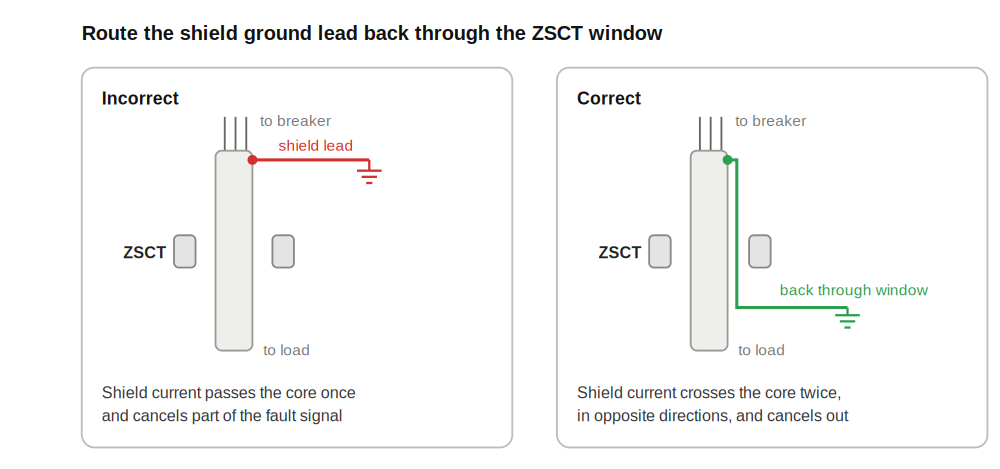
Nothing on the relay display hints at a wrongly routed shield lead. The relay simply under-reads, which is why the error tends to surface only after a fault has been cleared late.
The equipment grounding conductor should not pass through the window together with the phases either, for the same reason.
What happens if the neutral is bonded to ground downstream of the ZSCT?
In a four-wire system the neutral has to pass through the window with the phase conductors; otherwise normal single-phase load current returning on the neutral looks like a ground fault. Including the neutral solves that, but only if neutral and ground are bonded in one place upstream of the sensor, usually at the service entrance or the supply transformer.
An extra neutral-to-ground bond downstream, such as a bonding jumper left in a subpanel or inside equipment, creates a parallel return path. Part of the normal neutral current then returns on the grounding conductor outside the window and shows up as false residual current. During a real ground fault, part of the fault current may return on the neutral through the window and reduce the measured signal. The result can be nuisance tripping, a desensitized relay, or both, which is why checking for a single neutral-to-ground bond is one of the first steps when a four-wire ground-fault scheme misbehaves.
This matters in the US because ground-fault protection of equipment (GFPE) on larger services can use zero-sequence sensing. For example, NEC 230.95 in the 2023 edition requires GFPE for certain solidly grounded wye services rated 1000 A or more. Requirements depend on the adopted NEC edition and the local jurisdiction.
Conductor geometry and stray fields
Geometry plays a part too. Single-conductor cables spread unevenly across a large window, or bunched against one side, can produce a small false output under heavy load because no core is perfectly uniform. Grouping the conductors, keeping them roughly centered and choosing a window that fits the bundle without large gaps all help. Stray fields from a nearby high-current bus or another feeder’s cables can also reach the core, and a modest distance from those sources usually solves it.
VFD feeders and high-frequency leakage
Variable-frequency drives are another common source of nuisance residual current. Their EMC filters, switching edges and motor-cable capacitance can send high-frequency current to ground even when no insulation fault is present. On VFD feeders, relay filtering, pickup level and time delay therefore have to be coordinated with the drive and cable installation rather than set as low as possible.
CT secondary safety
As with any current transformer, the secondary should not be left open when significant primary residual current may be present. Under normal balanced load a ZSCT carries very little net primary excitation, but during a ground fault its secondary can still develop hazardous voltage if left open. Short the secondary at a test block or terminal before a relay is removed or rewired.
Solid-core or split-core ZSCT: which one fits the job?
Solid core suits new installations, while split core suits retrofits where cables cannot be disconnected.
Solid core is the cleaner option when the cable can still be pulled through the CT, and it is generally a little more accurate and stable. For a retrofit, that may be impossible. A split core clamps around cables already in place, which makes it popular for adding ground-fault monitoring during a planned outage, although its mating surfaces need more attention: dirt or poor alignment can introduce measurement error.
How do you select a zero sequence CT for a specific relay?
Start from the relay’s ground CT input requirements, then match window size, core type and secondary lead length to the installation.
There is no single “standard” ZSCT ratio. Many relay manufacturers specify which CT ratios or models their sensitive ground inputs are designed for, and some relays expect a dedicated sensor with an unusual output, such as 50:0.025 A, rather than a conventional 1 A or 5 A secondary. Ratios such as 50:1 or 100:1 are used in some applications, while other relays require dedicated sensors with much higher turns ratios or milliampere-level outputs. Compatibility with the exact relay model should be confirmed before ordering.
Before asking a supplier for a ZSCT, have four things ready:
- Relay model and its ground CT input requirements (ratio, burden, accuracy)
- Window size that fits the actual cable bundle, including lugs if the CT slides over terminated ends
- Solid or split core, depending on whether cables can be pulled through
- Secondary lead length to the relay, since long runs add burden a small toroid may not tolerate
One more point is easy to overlook: insulation. When a ZSCT is mounted over insulated cables, its own insulation level is often low-voltage class, because the cable insulation forms the main barrier. A damaged jacket inside the window is therefore a genuine concern.
For milliampere-secondary sensors, the North American reference is IEEE C57.13.7, which covers current transformers with a maximum secondary current of 250 mA. Conventional instrument CTs fall under IEEE C57.13, and IEC 61869-2 is the international counterpart.
Need help matching a ZSCT to your relay? Send us the relay model, cable diameter and required pickup current through our product page.
Frequently asked questions about zero sequence CTs
Does the neutral pass through a ZSCT?
Yes, in a four-wire system. All current-carrying conductors, including the neutral, go through the window; the equipment grounding conductor does not.
Can a ZSCT detect phase-to-phase faults?
No. Phase-to-phase and balanced three-phase faults produce no residual current, so the ZSCT stays quiet. Phase overcurrent protection covers those faults.
How do you test a ZSCT during commissioning?
Pass an insulated test conductor through the ZSCT window and inject a known primary current. This checks the sensor, secondary wiring and relay input together. Verify the measured residual current and pickup point against the relay settings and the CT ratio, and follow the relay and CT manufacturers’ test instructions before performing primary injection.
What ZSCT ratio should I use?
The one the relay’s ground CT input is designed for. Relay documentation usually names compatible ratios or sensor models, and that requirement comes before any rule of thumb.
What is the difference between a ZSCT and an RCD or GFCI?
An RCD or GFCI combines residual-current sensing and tripping in one protective device, typically at a defined residual-current rating. A ZSCT is only the sensor and feeds a separate relay, which may provide adjustable pickup and time delay.
Most ZSCT trouble starts outside the ring
A zero sequence CT is about as simple as instrument transformers get: one core, one winding, no electrical connection to the primary at all. Its value comes from what it ignores. By staying deaf to balanced load current, it can register the faint leakage that tends to come before far more expensive failures, provided the shields, ground leads and cable routing around it are done right. When a scheme misbehaves, that wiring, the neutral bonding and the relay settings are usually the first places to look, long before the ring itself.
Zero sequence CTs in our lineup
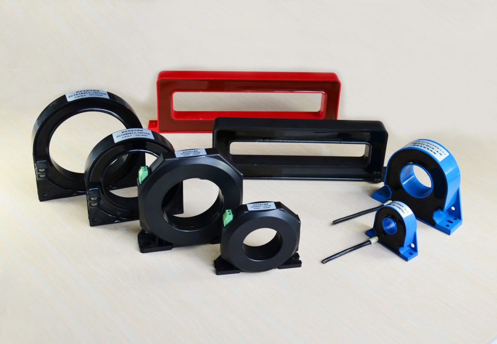
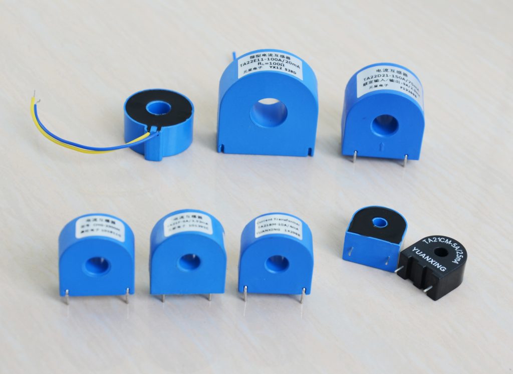
At Yuanxing, we design and manufacture zero sequence current transformers for ground-fault detection and residual-current monitoring. For panel and cable installations, our range includes round-window ZCTA and ZCTSA series (30 to 200 mm, accuracy class 0.2 or 0.5) and rectangular-window ZCTB and ZCTSB series (from 112 × 25 to 320 × 48 mm, class 1.0 or 3.0), all with 1000:1 or 2000:1 turns ratios, a 10 mA to 20 A input range and a burden below 100 Ω. For equipment makers, the compact ZTA series offers voltage-output sensors with inner diameters from 3.6 to 17 mm, rated input currents from 15 to 200 A, a 10 mA to 1 A zero-sequence range and operation from 50 to 400 Hz, intended for integration into relays, leakage-protection modules and other devices.
All of these series are intended for sensitive residual-current and ground-fault monitoring, such as ground-fault and leakage relays and residual current monitors, where the expected primary residual current falls within the stated range. They should not be selected for high-current MV protection applications on the basis of the MV examples discussed above.
The 1000:1 and 2000:1 ratios of the ZCTA, ZCTSA, ZCTB and ZCTSB series also put them in a different class than the 50:1 or 100:1 examples mentioned earlier: they deliver a milliampere-level secondary, the kind of signal that relays and monitors with mA inputs are built for. Because we make our transformers in-house, we can also build to a project’s needs when the catalog doesn’t quite fit, for example a nonstandard window for a large cable bundle or a different output characteristic.
Request a ZSCT recommendation. Send us your relay model, cable arrangement, required residual-current range and installation dimensions, and our engineers will suggest a suitable model. View our zero sequence CT range